What’s Industrial Automation ?
Industrial automation is the use of control systems, such as computers or robots, and information technologies for handling different processes and machineries in an industry to replace a human being. It is the second step beyond mechanization in the scope of industrialization.
Automation describes a wide range of technologies that reduce human intervention in processes. Human intervention is reduced by predetermining decision criteria, subprocess relationships, and related actions — and embodying those predetermination in machines.
Automation, includes the use of various equipment and control systems such as machinery, processes in factories, boilers, and heat-treating ovens, switching on telephone networks, steering, and stabilization of ships, aircraft, and other applications and vehicles with reduced human intervention.
Automation covers applications ranging from a household thermostat controlling a boiler, to a large industrial control system with tens of thousands of input measurements and output control signals. Automation has also found space in the banking sector. In control complexity, it can range from simple on-off control to multi-variable high-level algorithms.
In the simplest type of an automatic control loop, a controller compares a measured value of a process with a desired set value and processes the resulting error signal to change some input to the process, in such a way that the process stays at its set point despite disturbances. This closed-loop control is an application of negative feedback to a system. The mathematical basis of control theory was begun in the 18th century and advanced rapidly in the 20th
Automation has been achieved by various means including mechanical, hydraulic, pneumatic, electrical, electronic devices, and computers, usually in combination. Complicated systems, such as modern factories, airplanes, and ships typically use all these combined techniques. The benefit of automation includes labor savings, reducing waste, savings in electricity costs, savings in material costs, and improvements to quality, accuracy, and precision.
The World Bank’s World Development Report 2019 shows evidence that the new industries and jobs in the technology sector outweigh the economic effects of workers being displaced by automation.
Job losses and downward mobility blamed on Automation has been cited as one of many factors in the resurgence of nationalist, protectionist and populist politics in the US, UK and France, among other countries since the 2010s.
The term automation, inspired by the earlier word automatic (coming from automaton), was not widely used before 1947, when Ford established an automation department. It was during this time that industry was rapidly adopting feedback controllers, which were introduced in the 1930s.
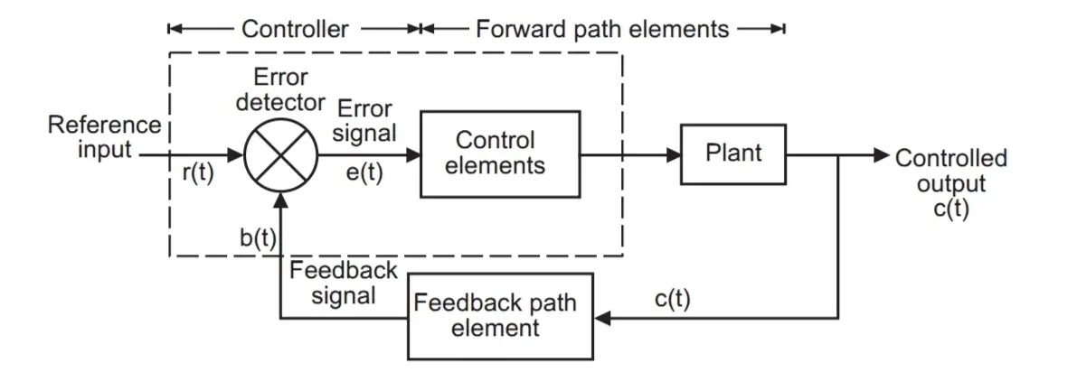
Open-loop and closed-loop (feedback) control
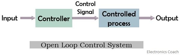
Fundamentally, there are two types of control loops: open-loop control, and closed-loop control.
In open-loop control, the control action from the controller is independent of the “process output” (or “controlled process variable”). A good example of this is a central heating boiler controlled only by a timer, so that heat is applied for a constant time, regardless of the temperature of the building. (The control action is switching the boiler off and on. The process output is building temperature.)
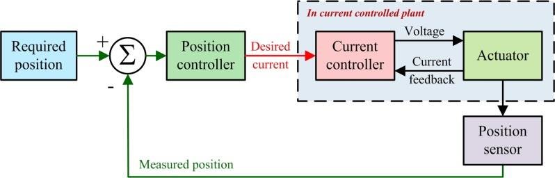
In closed-loop control, the control action from the controller is dependent on the process output. In the case of the boiler analogy, this would include a temperature sensor to monitor the building temperature, and thereby feed a signal back to the controller to ensure it maintains the building at the temperature set on the thermostat. A closed-loop controller, therefore, has a feedback loop that ensures the controller exerts a control action to give a process output equal to the “reference input” or “set point”. For this reason, closed-loop control is also called feedback control.[12]
The definition of a closed-loop control system according to the British Standard Institution is ‘a control system possessing monitoring feedback, the deviation signal formed as a result of this feedback being used to control the action of a final control element in such a way as to tend to reduce the deviation to zero.’[13]
Likewise, a Feedback Control System is a system that tends to maintain a prescribed relationship of one system variable to another by comparing functions of these variables and using the difference as a means of control.[13] The advanced type of automation that revolutionized manufacturing, aircraft, communications, and other industries, is feedback control, which is usually continuous and involves taking measurements using a sensor and making calculated adjustments to keep the measured variable within a set range.[14] The theoretical basis of closed-loop automation is control theory.
Open Loop Control System : –
Close Loop Control System
Discrete control (on/off)
One of the simplest types of control is on-off control. An example is a thermostat used on household appliances which either open or close an electrical contact. (Thermostats were originally developed as true feedback-control mechanisms rather than the on-off common household appliance thermostat.)
Sequence control, in which a programmed sequence of discrete operations is performed, often based on system logic that involves system states. An elevator control system is an example of sequence control.
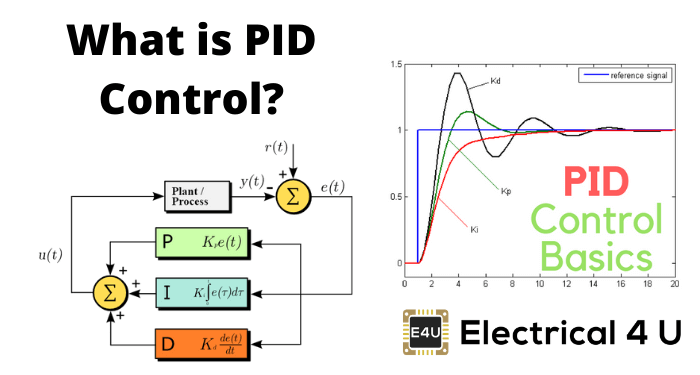
PID controller
A proportional–integral–derivative controller (PID controller) is a control loop feedback mechanism (controller) widely used in industrial control systems.
In a PID loop, the controller continuously calculates an error value e ( t ) {\displaystyle e(t)}  as the difference between a desired setpoint and a measured process variable and applies a correction based on proportional, integral, and derivative terms, respectively (sometimes denoted P, I, and D) which give their name to the controller type.
The theoretical understanding and application date from the 1920s, and they are implemented in nearly all analog control systems; originally in mechanical controllers, and then using discrete electronics and latterly in industrial process computers.
Sequential control and logical sequence or system state control
Sequential control may be either to a fixed sequence or to a logical one that will perform different actions depending on various system states. An example of an adjustable but otherwise fixed sequence is a timer on a lawn sprinkler.
States refer to the various conditions that can occur in a use or sequence scenario of the system. An example is an elevator, which uses logic based on the system state to perform certain actions in response to its state and operator input. For example, if the operator presses the floor n button, the system will respond depending on whether the elevator is stopped or moving, going up or down, or if the door is open or closed, and other conditions.
Early development of sequential control was relay logic, by which electrical relays engage electrical contacts which either start or interrupt power to a device. Relays were first used in telegraph networks before being developed for controlling other devices, such as when starting and stopping industrial-sized electric motors or opening and closing solenoid valves. Using relays for control purposes allowed event-driven control, where actions could be triggered out of sequence, in response to external events. These were more flexible in their response than the rigid single-sequence cam timers. More complicated examples involved maintaining safe sequences for devices such as swing bridge controls, where a lock bolt needed to be disengaged before the bridge could be moved, and the lock bolt could not be released until the safety gates had already been closed.
The total number of relays and cam timers can number into the hundreds or even thousands in some factories. Early programming techniques and languages were needed to make such systems manageable, one of the first being ladder logic, where diagrams of the interconnected relays resembled the rungs of a ladder. Special computers called programmable logic controllers were later designed to replace these collections of hardware with a single, more easily re-programmed unit.
In a typical hard wired motor start and stop circuit (called a control circuit) a motor is started by pushing a “Start” or “Run” button that activates a pair of electrical relays. The “lock-in” relay locks in contacts that keep the control circuit energized when the push-button is released. (The start button is a normally open contact and the stop button is normally closed contact.) Another relay energizes a switch that powers the device that throws the motor starter switch (three sets of contacts for three-phase industrial power) in the main power circuit. Large motors use high voltage and experience high in-rush current, making speed important in making and breaking contact. This can be dangerous for personnel and property with manual switches. The “lock-in” contacts in the start circuit and the main power contacts for the motor are held engaged by their respective electromagnets until a “stop” or “off” button is pressed, which de-energizes the lock in relay.
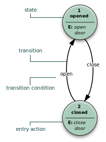
This state diagram shows how UML can be used for designing a door system that can only be opened and closed.
Commonly interlocks are added to a control circuit. Suppose that the motor in the example is powering machinery that has a critical need for lubrication. In this case, an interlock could be added to ensure that the oil pump is running before the motor starts. Timers, limit switches, and electric eyes are other common elements in control circuits.
Solenoid valves are widely used on compressed air or hydraulic fluid for powering actuators on mechanical components. While motors are used to supply continuous rotary motion, actuators are typically a better choice for intermittently creating a limited range of movement for a mechanical component, such as moving various mechanical arms, opening or closing valves, raising heavy press-rolls, applying pressure to presses.
Computer control
Computers can perform both sequential control and feedback control, and typically a single computer will do both in an industrial application. Programmable logic controllers (PLCs) are a type of special-purpose microprocessor that replaced many hardware components such as timers and drum sequencers used in relay logic type systems. General-purpose process control computers have increasingly replaced stand-alone controllers, with a single computer able to perform the operations of hundreds of controllers. Process control computers can process data from a network of PLCs, instruments, and controllers to implement typical (such as PID) control of many individual variables or, in some cases, to implement complex control algorithms using multiple inputs and mathematical manipulations. They can also analyze data and create real-time graphical displays for operators and run reports for operators, engineers, and management.
Control of an automated teller machine (ATM) is an example of an interactive process in which a computer will perform a logic derived response to a user selection based on information retrieved from a networked database. The ATM process has similarities with other online transaction processes. The different logical responses are called scenarios. Such processes are typically designed with the aid of use cases and flowcharts, which guide the writing of the software code. The earliest feedback control mechanism was the water clock invented by Greek engineer Ctesibius (285–222 BC).